Mini City - Part I Step 1: Interactive Road Tool
- kyle890229
- Jan 23, 2023
- 3 min read
Updated: Feb 2, 2023

The first two weeks I have been working on creating the road tool for the based on the city generator since everything will be based on it. I had some trouble in the beginning thinking about how I want to approach the tool. How I decided to create the tool is the user will input curves as the road network. The road tool will generate a mesh of the road based on the input curves.
The first hurdle I faced while creating the road tool is solving the intersections. There are some videos on YouTube talking about city generator, but they didn't talk in detail how they solve the intersections. This road generator tutorial is the only one I found that's helpful for solving the problem I have.
However, there are some issues with the tutorial. The first problem is that it only works for solving one intersection input at a time, but I wanted to create a tool that's solving multiple intersection input together. Therefore, I had to figure out a way to isolate each intersection to solve. The second issue I had faced was that he used VOP a lot, and sometimes he complicated things with more steps than it needed. I translate and simplify most of his VOP steps into VEX.
Here are my steps of creating the road tool based on the tutorial:
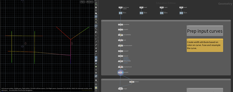
The first step is preparing the input curves for intersection calculation. User can put in three colors of curves, Red, Green, and Blue, to change the number of lanes. Red is the widest and blue is the narrowest. Additionally, user is able to adjust the number of the lanes, and the width of each lane. After that, the curve will then be stitched together in order find the intersection in the next step.

The second step is removing primitives that is not the intersection. User can adjust the distance of the intersection.

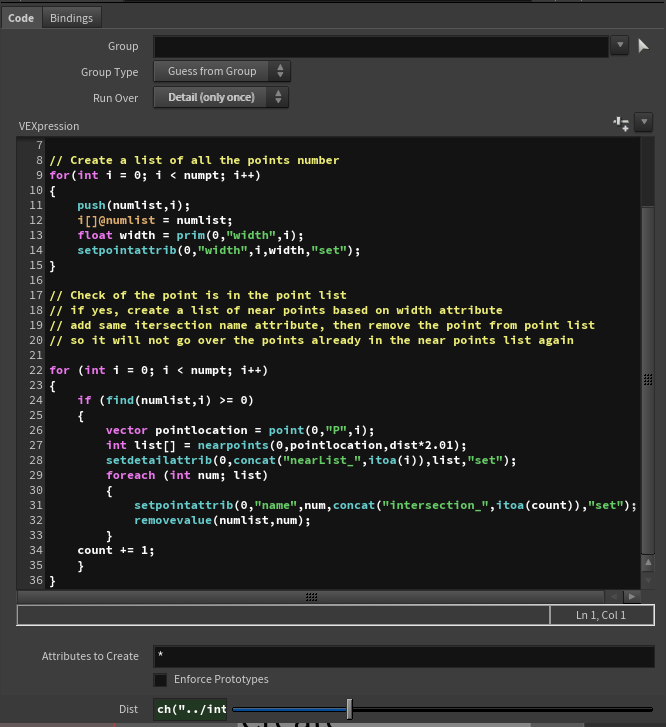
The third part was what took me the longest time because I had to figure out a way to isolate each intersection, and re-order the point number clockwise or counterclockwise. The way I solve this issue is by using the nearpoints function. I started by creating a big list of all the intersection points number. For each number in the big list, create a list of near points which are the points in the same intersection. After that add a nearList_# attribute for all the points in the intersection list, and then remove the number from the big number list, so it wouldn't go over points that already been assigned an intersection attribute. After solving all the intersections, it can then go through a for-each loop to loop over each intersetion by the nearList_# attribute.
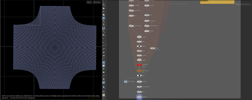
The fourth step is creating the mesh for the intersection. This part isn't very different from the tutorial other than changing from VOP to VEX.

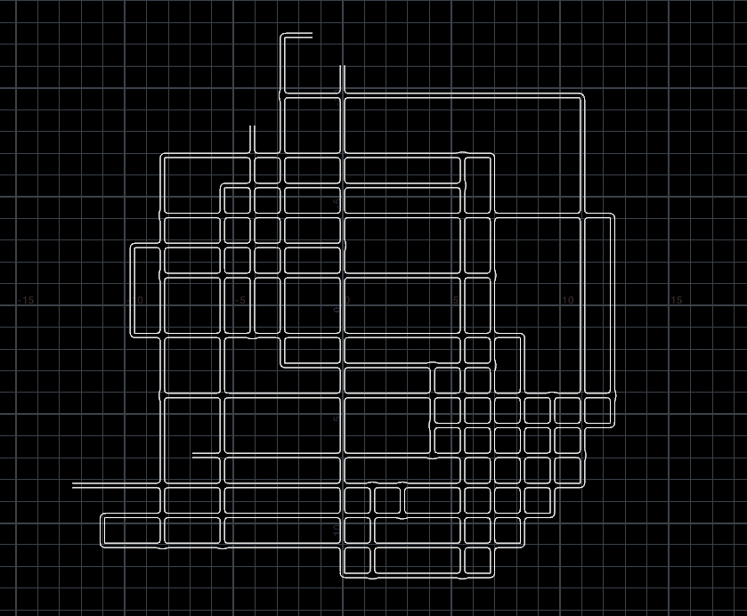
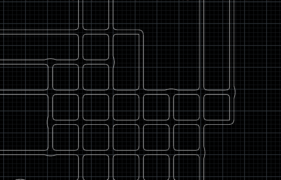
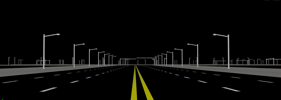
Here is another example of the road tool with a grid input. The subnet of the road tool currently has two outputs, the road mesh, and curves of the edge of the road which can be used to create pavements, and road furniture.

However, there is an issue with the T-shape intersection. The intersection solving process was adding the width to the point position based on the cross product of the point normal and up vector. The middle center point will combine both points cross product. Consequently, if the side of edge is flat, it would looks bumped because the width was doubled.
The solution I found was by comparing the length of two side edges to the longest side.
In a triangle, A + B should always be bigger than C. In contrast, if the triangle is nearly flat or if it's a line, A + B should be equal or close to C.

With this concept implemented in to VEX, I was able to only add width one time to the edges that is flat or close to flat to solve the curved T-shape issue. I calculated the distance of each edge and use the formula above to get the factor value. It will only add the width 1 times if the factor value is close to 1.


Comments